

Each connector can be identified as:
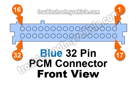
- C1 Blue (32 Pin Connector).
- C2 Red (32 Pin Connector).
- C3 Clear -or Grey- (32 Pin Connector).
- C4 Black (24 Pin Connector).
The symbol: <-> means that the Connector Pin # will have one of two different wires DEPENDING on the actual year of your vehicle or whether your it's equipped with a 4.3L, 5.0L, 5.7L, etc.
| C1 (Blue) PCM 32 Pin Connector | ||
|---|---|---|
| Pin | Wire Color | Description |
| 1 | --- | Empty |
| 2 | --- | Empty |
| 3 | Brown w/ White stripe | 1X Cam (CMP) Sensor Signal |
| 4 | --- | Empty |
| 5 | --- | Empty |
| 6 | --- | Empty |
| 7 | Tan | HO2S Low Bank 2 Sensor 1 |
| 8 | Pink w/ Black stripe | Cam (CMP) Sensor Ground (Low) |
| 9 | Purple | Fuel Gauge (Fuel Level Output) |
| 10 <-> | --- | Empty (1998 Only) |
| 10 <-> | Tan w/ Black stripe | TCC Control Solenoid (1999 Only) |
| 11 | --- | Empty |
| 12 | --- | Empty |
| 13 | --- | Empty |
| 14 | Brown | AIR Relay Control (California Only) |
| 15 | Yellow w/ Black stripe | Vehicle Speed Sensor (VSS) |
| 16 | --- | Empty |
| 17 | --- | Empty |
| 18 <-> | Purple w/ White stripe | Dual Tank Fuel Module (1998 Only) |
| 18 <-> | --- | Empty (1999 Only) |
| 19 | Purple w/ White stripe | HO2S High Bank 1 Sensor 1 |
| 20 <-> | Purple | HO2S High Bank 1 Sensor 2 (1998 Only) |
| 20 <-> | Purple | HO2S High Bank 2 Sensor 2 w/out C6P -under 8600 GVW (1999 Only) |
| 20 <-> | Purple | HO2S High Bank 1 Sensor 2 w C6P -over 8600 GVW (1999 Only) |
| 21 | Purple | HO2S High Bank 2 Sensor 1 |
| 22 <-> | Purple w/ White stripe | HO2S High Bank 2 Sensor 2 (1998 Only) |
| 22 <-> | Purple w/ White stripe | HO2S High Bank 2 Sensor 2 w/ C6P -over 8600 GVW (1999 Only) |
| 22 <-> | Purple w/ White stripe | HO2S High Bank 1 Sensor 2 w C6P -under 8600 GVW (1999 Only) |
| 23 | --- | Empty |
| 24 <-> | Tan | HO2S Low Bank 1 Sensor 2 (1998 Only) |
| 24 <-> | Tan | HO2S Low Bank 2 Sensor 2 w/out C6P -under 8600 GVW (1999 Only) |
| 24 <-> | Tan | HO2S Low Bank 1 Sensor 2 w/ C6P -over 8600 GVW (1999 Only) |
| 25 | Tan w/ White stripe | HO2S Low Bank 1 Sensor 1 |
| 26 <-> | Tan w/ White stripe | HO2S Low Bank 2 Sensor 2 (1998 Only) |
| 26 <-> | Tan w/ White stripe | HO2S Low Bank 2 Sensor 2 w/ C6P -over 8600 GVW (1999 Only) |
| 26 <-> | Tan w/ White stripe | HO2S Low Bank 1 Sensor 2 w/out C6P -under 8600 GVW (1999 Only) |
| 27 | --- | Empty |
| 28 | Purple | Crank (CKP) Sensor Ground (Low) |
| 29 | Light Green w/ Black | Vehicle Speed Sensor (VSS) Low |
| 30 | Purple w/ White stripe | Vehicle Speed Sensor (VSS) Signal |
| 31 | Yellow | 4X Crank (CKP) Sensor Signal |
| 32 | --- | Empty |
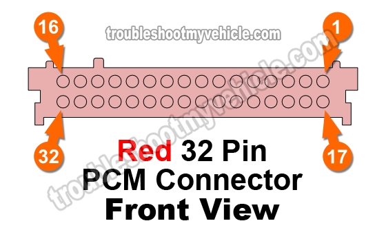
| C2 (Red) PCM 32 Pin Connector | ||
|---|---|---|
| Pin | Wire Color | Description |
| 1 | --- | Empty |
| 2 | White | Canister Vent Solenoid Control |
| 3 | --- | Empty |
| 4 | Yellow w/ Black stripe | 2-3 Shift Solenoid Control |
| 5 | --- | Empty |
| 6 | Light Green | 1-2 Shift Solenoid Control |
| 7 | Brown | PWM TCC Solenoid Control |
| 8 | Black | Injector #1 Control |
| 9 | Dark Blue w/ White stripe | Injector #8 Control |
| 10 | Brown | EGR Pintle Position |
| 11 | Light Green w/ Black stripe | Injector #2 Control |
| 12 | Red w/ Black wire | Injector #7 Control |
| 13 | Light Green w/ White stripe | Idle Air Control (IAC) B High |
| 14 | Light Blue w/ White stripe | Idle Air Control (IAC) A High |
| 15 | Black w/ White stripe | Injector #5 Control |
| 16 | Yellow w/ Black stripe | Injector #6 Control |
| 17 | --- | Empty |
| 18 | --- | Empty |
| 19 | Dark Blue | Knock Sensor Signal |
| 20 | --- | Empty |
| 21 | Light Green | Manifold Absolute Pressure (MAP) Signal |
| 22 | Tan | Intake Air Temp (IAT) Signal |
| 23 | Yellow | Engine Coolant Temp (ECT) Signal |
| 24 | Dark Blue | Throttle Position Sensor (TPS) Signal |
| 25 | Dark Green | Fuel Tank Vacuum Sensor Signal |
| 26 | --- | Empty |
| 27 | Yellow w/ Black stripe | TFT Signal (Automatic Transmission Only) |
| 28 | Yellow | Mass Air Flow (MAF) Sensor Signal |
| 29 | Light Green w/ Black stripe | Idle Air Control (IAC) B Low |
| 30 | Light Blue w/ Black stripe | Idle Air Control (IAC) A Low |
| 31 | Light Blue w/ Black stripe | Injector #4 Control |
| 32 | Pink w/ Black stripe | Injector #3 Control |

| C3 (Grey -Clear-) PCM 32 Pin Connector | ||
|---|---|---|
| Pin | Wire Color | Description |
| 1 | Dark Green w/ White stripe | A/C Compressor Clutch Relay Control |
| 2 | Dark Green w/ White stripe | Purge Canister Solenoid |
| 3 | --- | Empty |
| 4 | Black | Engine Coolant Temp (ECT) and Throttle Position Sensor (TPS) Ground |
| 5 | --- | Empty |
| 6 | Red w/ Black stripe | PC Solenoid Valve High |
| 7 | Dark Blue w/ White stripe | Input Speed Sensor Low |
| 8 | Red w/ Black stripe | Input Speed Sensor High |
| 9 | White | Ignition Control Module (ICM) Control |
| 10 | --- | Empty |
| 11 | Red | Transmission Range Signal C |
| 12 | Gray | 5 Volt Reference |
| 13 | Purple w/ White stripe | Fuel Level Module (Single Tank) |
| 14 | Dark Blue | A/C Recirculation Signal |
| 15 | --- | Empty |
| 16 | Light Blue w/ White stripe | PC Solenoid Low (Automatic Transmission Only) |
| 17 | Black w/ White stripe | System Ground |
| 18 | Black w/ White stripe | System Ground |
| 19 | Black | Sensor Ground (IAT/MAP/EGR, etc.) |
| 20 | --- | Empty |
| 21 | Orange | 12 Volt Battery Feed |
| 22 | Dark Blue | Transmission Range Signal B |
| 23 | Pink | Transmission Range Signal A |
| 24 | --- | Not Used |
| 25 | Dark Green w/ White stripe | A/C Request Signal |
| 26 | --- | Empty |
| 27 | Grey | EGR, MAP 5 Volt Reference |
| 28 | --- | Empty |
| 29 | --- | Empty |
| 30 | Dark Green | A/C Compressor Cycling Switch Signal |
| 31 | --- | Empty |
| 32 | --- | Empty |
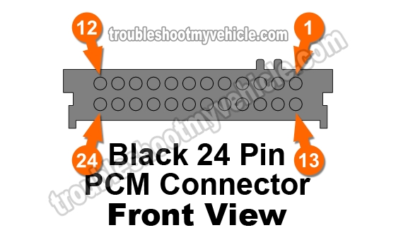
| C4 (Black) PCM 24 Pin Connector | ||
|---|---|---|
| Pin | Wire Color | Description |
| 1 | Dark Green w/ White stripe | Fuel Pump Relay Control |
| 2 | --- | Empty |
| 3 | Dark Green w/ White stripe | Vehicle Speed Sensor (VSS) Output Signal (TCCM, Radio, Cruise) |
| 4 | Dark Green | Vehicle Speed Sensor (VSS) Output Signal (Speedometer) |
| 5 | Brown w/ White stripe | Malfunction Indicator Light (MIL) ...Check Engine Light |
| 6 | --- | Empty |
| 7 | Dark Green | Inlet Air Actuator (Recirculation Door Motor) Control |
| 8 | --- | Empty |
| 9 | Dark Blue | Auxiliary Electric Cooling Fan |
| 10 | Purple | Brake Switch Signal |
| 11 | Purple | Serial Data (Class 2) |
| 12 | Black | Dual Fuel Module Return |
| 13 | Brown | 12 Volt Ignition Feed |
| 14 | --- | Empty |
| 15 <-> | --- | Empty (1998 Only) |
| 15 <-> | Tan w/ Black | Shift Light (Manual Transmission -1999 Only) |
| 16 | Red | EGR Valve Solenoid Control |
| 17 | --- | Empty |
| 18 | Pink | 12 Volt Ignition Feed |
| 19 | Black w/ White stripe | 4WD Engaged Signal (Wheel Lock Input) |
| 20 | White | EGR Valve Solenoid Control |
| 21 | --- | Empty |
| 22 <-> | --- | Empty (1998 Only) |
| 22 <-> | Brown w/ White stripe | CPP Switch Signal (Manual Transmission -1999 Only) |
| 23 | Gray w/ Black stripe | Transfer Case High Low Switch |
| 24 | Light Blue w/ Black stripe | Cruise Engaged Signal |