In this post we will take a closer look at programming BMW electronic components using the WinKFP program. This article will not provide instructions for installing the program, instructions for use, since all this information is on the Internet, and WinKFP is part of the BMW Standard Tools program package, including Ediabas. BMW Standard Tools installation instructions, you can find here . If anyone does not have this software package, then carefully study and do everything according to the instructions. Well, do not forget that correctly installed and configured programs for diagnosing / coding / programming BMW ECUs are already half the success, and the first step to independent work with BMW ECUs.
In this post, there will be tips, cautions, general guidance in choosing, searching, updating the necessary firmware for BMW electronic components.
On the example of my BMW E39 car, we will look at how to update the firmware of the electronic engine control unit (DME), as well as where to look and how to get the necessary information.
So, since the catalyst has been removed from my car, let's say I wanted to find out what firmware of the DME block I have, find out if there are other firmware for my engine control unit, maybe we want to flash on Euro2 or on a car without a catalyst:
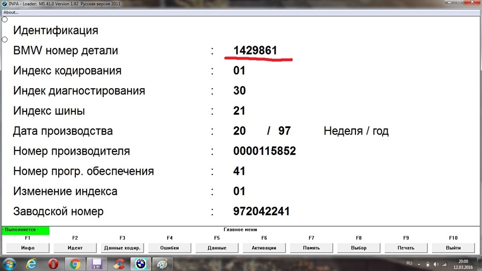
— First, find out the part number of the DME unit. To do this, we use, for example, the INPA program, which is fast and convenient, and is also included in the BMW Standard Tools software package. We connect to the car, turn on the ignition, start the Inpa program, select the car model, select the engine, press F2 (identification), I think this should not be a problem, I described in more detail how to do this in this topic. We get the following information:
Zoom
DME Block Identification
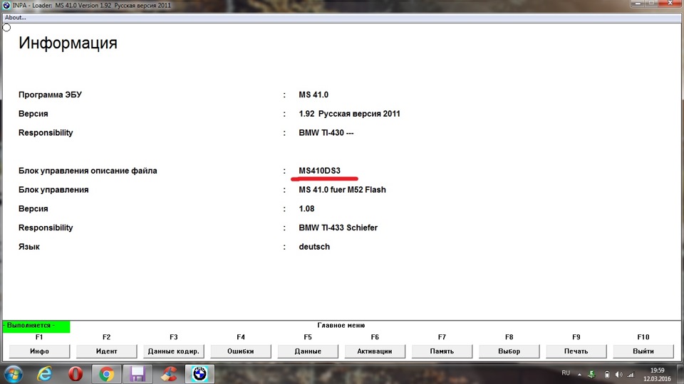
The top line, 1 429 861 , this is the part number of our unit. To find out the program number of the DME electronic unit, select the information (F1) item in INPE, see the MS41 number:
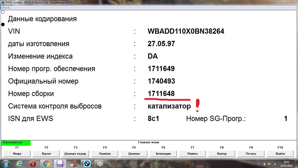
To find out the current version of the firmware of the block, select the encoding item (F3) in INPA, we get the following information:
We see the number of the "real" firmware 1711648, and also pay attention to the fact that the firmware is for a car with a catalyst.
So, we learned the part number of the block we are interested in, the program number of the block and the firmware number, we will need these data in the future, therefore we save them.
Next, go to ETK we drive in the part number that we recognized, select "DME ECU programmed", and get a list of available block firmware, we see confirmation of the information that we received above, our firmware for cars with a catalyst, block program number MS41.0. If for some reason someone doesn’t succeed in finding the list of available stock firmware by the unit part number, you can go the other way, go to the main ETK , or manually select the BMW you are interested in by model, engine, steering wheel, gearbox, production date, or enter the BMW VIN number of the body, and go to the group parts of our car as a result, select the item "engine electrical equipment", find the line "DME ECU programmed", and finally again get into the list of ECU firmware.
I want to draw your attention to the fact that I entered and took all the data from my own BMW, accordingly, you will need to choose your data, the numbers you will also have others as a result.
In our list of available ECU firmware, for my M52 engine, we see that there are no stock firmware for Euro2, there is no firmware for a car either, so the firmware of my unit will essentially not give me anything, since the catalyst is cut out and lambd after cut out I don’t have a catalyst, but the lambda installed before the catalyst, for the presence of generally living cat on the side. In fact, it is, on engines with one Vanos, there is no stock firmware for Euro2 and no bezkat, they appeared only on engines fresh M52TU, M54 and so on. For MS41, it remains only by editing the stock firmware, fill it in a block, but more about that in another entry.
Consider an example of the available firmware for the M52TU motor, with the program number of the MS42 block, actually list of available firmware in comparison with MS41. Now we see in the list that it is possible to flash this motor (MS42) for Euro 2 and a car without a catalyst (no catalyst). We draw our attention to the description of the firmware, in the tab additionally, to the availability of options 168 (Euro 2 — EU 2 exhaust gas aftertreatment system), 199 (No catalyst — bezkat), 861 (without EOBD — disabling all exhaust gas tests in general), if you have automatic transmission then another option 205. There are firmware, with several options at once. We select the necessary firmware number for ourselves. Namely, the last 7 digits, they are useful to us for the WinKFP program.
I advise you to study the instructions for using the WinKFP program, it will also protect and give you answers to many questions. Here is the actual detailed instruction in pdf format, in Russian, download and study.
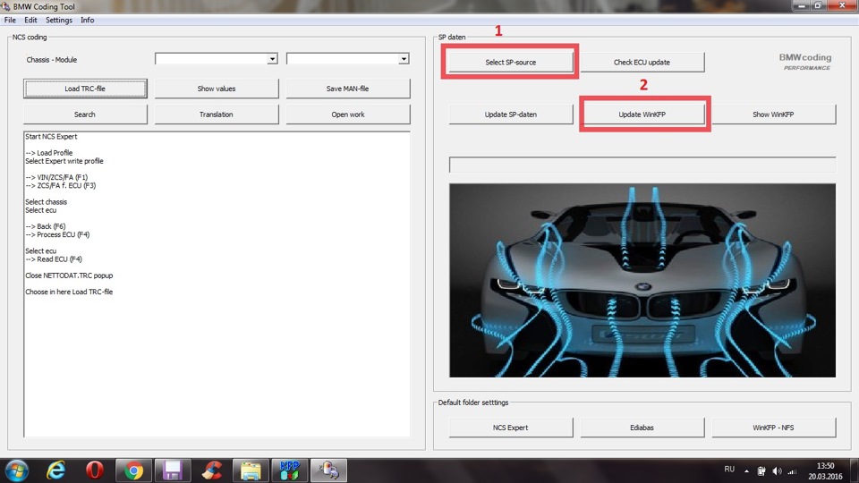
Before working with WinKFP, we need to import these ISTA files for the bodies with which we are going to work. To do this, download the files for the required BMW SP-Daten body (latest and current at the time of writing article 2.55), link to the rutreker. You can import files manually by copying them to the appropriate directories (video and instructions are on the Internet how to do this), but I suggest I personally use the convenient BMW Coding Tool program, everything is simple and clear, download , launch, specify the path to the downloaded body SP-Daten files, import, wait for the import to finish:
Zoom
BMW Coding Tool, click on the button at number 1, then 2
Please also take into account the fact that you need to import data only for the body with which we will work, for example, we were going to flash E39, we imported data for E39, next time we want to work with the E46 body, we imported data for the E46 body, we launched the program and work, and so on. If we import data for all bodies at once, then in the ECU list there will be only the last body whose data was last imported. I think they figured out, there’s nothing complicated about that.
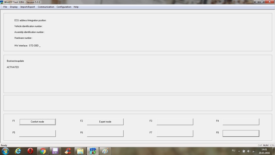
Our WinKFP is ready to work, we launch:
In the tab "Communication" in the line "HW Interface", you can configure the adapter with which we will connect to the car. In the "Configuration" tab, you can configure the language for working with the program (there is no Russian), and general program settings by reading the pdf instructions, the link above, setting up the program and removing unnecessary checkmarks will not be difficult. On my own, I note that UIF write after data is a record when programming data; UIF write after program — record when programming a program; UIF write in expert mode — recording in expert mode; UIF write in comfort mode — recording in comfort mode, in general, UIF is programmable information about the firmware version, date and mileage during programming, the space in the block is limited and you can record it only 13 times, so everyone decides for himself to leave checkmarks in the data points or not, and I also advise you to uncheck the box next to programming voltage — voltage supply during programming. The instructions for using the program also contain explanations on how to find out the number of the UIF block, and all the detailed explanations of the proposed actions, I see no reason to repeat.
The WinKFP program offers us to work in two modes, Comfort (Comfort mode) and Expert (Expert mode).
In comfort mode, there are 3 ways to flash the computer:
1) Enter ZUSB — enter the number of the new firmware (which we received from ETK) and WinKPF automatically determines and flashes the desired block;
2) Choose ZUSB — we ourselves select the block we need, then select the firmware from its list and program;
3) Update ZUSB — WinKPF itself will update the firmware in the selected computer.
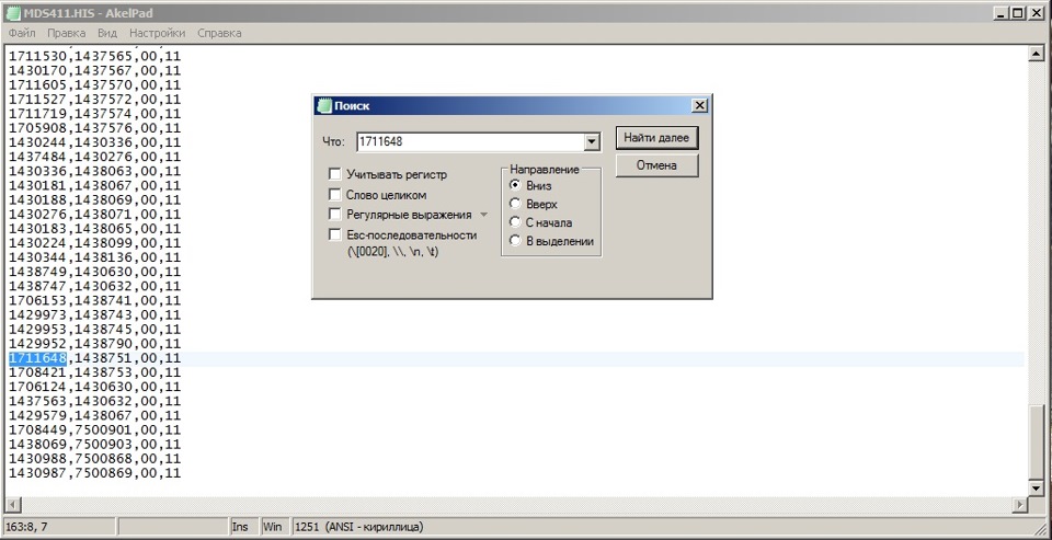
The evolution of firmware can be viewed in the file:
c: \ EC-APPS \ NFS \ DATA \ MDS411 \ MDS411.HIS
We open the file with a text editor, use the "find" function and drive in the number (for my MS41 unit, naturally you need to open the file in the folder of the required computer):
Zoom
Search firmware history
If we don’t know which block we need to select its number for firmware, then go along the path: C: \ ECAPPS \ NFS \ DATA \ GDATEN \ HWNR.DA2 , open the file with a text editor, use the "find" function "and drive in the part number of the block that we received in the INPA program (in my case it is 1429861), as a result:
Zoom
Search for the desired block by its part number
We determined that in WinKFP, we need to select the "mds411" block. This is for my car, as an example. And do not forget that in the INPA program, a little earlier, when reading information from the block, we received the same information (MS41).
Consider the firmware in comfortable mode by selecting "Choose ZUSB".
In the main window of the program, select "Comfort mode", enter your Vin auto (please note if all UIF checkboxes have been removed from the settings, then you do not need to enter VIN), then select "Choose ZUSB", look for the block line by the program number of the block, which we determined above, and select the desired firmware version from the list (firmware number, last 7 digits that we picked up in the ETK), like this:
Zoom
Block selection, firmware number, in comfort mode
After selecting the required data, click "Done", then "Program":
The final stage of selection before programming the unit
All block firmware has started, please note if UIF recording is enabled, then before starting programming, a window will open indicating how many times this block can be programmed, if everything is selected correctly, a blue bar with percentages will go, and the bar should go through twice, the first this is data programming, and the second is the program itself. During the firmware, the gear on the dashboard will light up, do not be afraid, this is normal.
If everything went well, and the blue bar went twice 100%, there will also be confirmation that the operation completed successfully. After flashing, it will be necessary to erase all errors from all electronic blocks of the car, since the program cuts off some blocks so that they do not hang the data bus, it will be necessary to erase all adaptations of the DME block, EWS and DME synchronization may also be required.
That's basically all, in this case there was an example of block firmware in comfortable mode, in the future there will be a record in the BZ, about firmware in expert mode (which you can learn more about in the program manual), in general, nothing complicated.
!
Well, now, let's talk a little about tips and cautions so that your work on block programming is successful. Firstly, all operations with your car, you do at your own peril and risk, you don’t need to rush anywhere and blame anyone, if something went wrong, you need to spend time, study everything in detail, and only then start working with the computer of the car, secondly, I repeat, you need to configure the programs correctly and study their instructions for working with BMW programs, you need to program the computer with the charger connected to the car in order to avoid battery discharge, which can lead to deplorable situations during the firmware. I also advise you to work with dealerships and BMW adapters when working with a car. No one except yourself is responsible, and will not give you a guarantee of what can happen when working with Chinese adapters, it is quite possible that everything will go off with a bang, but quite possibly not. If you are not confident in your actions, do not have experience and the corresponding software, software, equipment, then I advise you to contact people who are experienced in this matter.
Here are tips for working with ECU blocks from TIS:
A warning!
When programming on E38 and E39, remember that under certain conditions it is possible to cancel programming.
1. Cancellation of programming on vehicles with DSC III (E38 and E39 with a release date from September 1998 to December 1999)
2. Cancellation of programming on vehicles without DSC III
The reason for the cancellation of the programming may be the ignition off, a break in the connection between the DIS / MoDiC III or the voltage drop in the on-board network below 9 V during programming.
The concept of control units with flash ROM provides for the possibility of re-programming in case of cancellation.
To item 1. The control unit of the DSC III system interferes with the exchange of messages between the programmable control unit and DIS / MoDiC III during the programming process.
To item 2. The programmable control unit avoids communication with the DIS / MoDiC III due to interference on the diagnostic wire.
As a measure against canceling programming, it is recommended that you connect the charger before starting programming. Never connect or disconnect the charger during programming!
Avoid voltage drop in the on-board network during programming below 9 V.
To item 1. Proper programming is possible if the DSC III control unit is de-energized during programming. To do this, remove the following fuse:
E38: Fuse 17 (engine compartment)
E39: fuse 31 (glove box)
To item 2. If the programming is canceled, and the situation described under item 1 does not occur, then in this case it is recommended to disconnect the control unit for 1 minute.
Then connect the control unit, turn on the ignition and perform programming again.
If during the work with blocks any errors appeared in the WinKFP program, we remember the numbers of these errors and refer to the instructions for working with the program, at the end of the instruction there are tips for all possible errors and their possible causes.
This record has the promise that everyone can learn to work independently with his car, having at the same time, the equipment, the necessary software, and most importantly, the desire not to throw money away to hucksters, who sometimes break prices, and help and do not bring any benefit! With the only caveat, if you do not have anything from the above, then contact and choose people who will trust your car!
I also want to note if someone has any questions, or someone does not know how to use this or that program, throw your suggestions about what you would like to read in the BZ, what you want to understand, we will try to help and find ways and solution options. At least BMW has many programs, great opportunities.
Features when programming the DME MS41 ECU, described here .
DME MS43 ECU firmware video — here .
I’ll say it on my own, I tried to explain everything in detail and explain how I do it in each record of my BZ, so I get "a lot of letters", please understand and forgive. The best thanks for my work and time are likes, subscriptions and reposts, I will be grateful.)
Thank you all for your attention, especially those who mastered, service and take care of your cars, see you!
In my computer programming , I mentioned editing the stock firmware of the DME control unit, well, I think it's time to get to know it in closer. First of all, we'll figure it out in the basic maps and firmware settings that you need and can change to get the firmware you want. Let's analyze several ways how to read or write the firmware, the program for editing, we will give a brief guide to chip tuning.
Naturally, these records do not master everything, we will not go into details, and we will determine by the number of those who wish to know whether it is worth moving on, or it is not very interesting for anyone. The most important rule is to clearly understand and understand what you are doing, and what will be the result. In order to understand this in more detail, you need to be able to work with bytes, have the skill of working with programs, so we omit these concepts, since these are not the lessons of programmers, and the theory can drag on for a long time.
There are several ways to read / write the firmware of a block.
- Flash soldering from the board using a hair dryer and reading / writing via flash memory programmers. This method is the oldest and most time consuming. There is always the possibility of damaging the circuit tracks during disassembly or overheating the memory chip itself. Here is a short list of programmers that work with 29F400:
— Wilem
— Triton
— Autoprog
— galep
— biprog
— turboV6
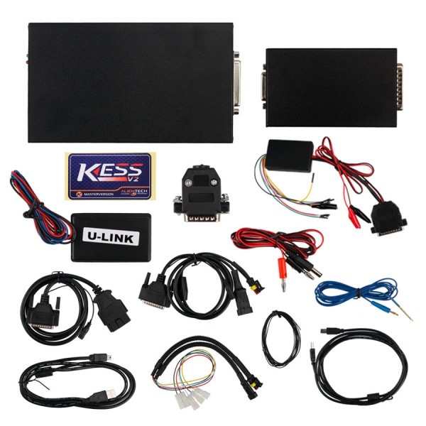
- KESS v2 . Professional boot ECU, is designed to read and write control units for cars, trucks and motorcycles through the diagnostic connector OBD2. Supports most types of computers and is compatible with almost all cars. Supports all major CAN / J1850 / K-LINE protocols. Has the function of automatic backup and recovery of the computer. Also used for chip tuning.
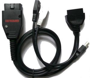
— Flasher Galetto 1260. Read / write part of the memory or the so-called area of calibrations. 1260l The flasher works through the k-line of the control unit. This method is convenient for quick reading, editing and writing a small area of memory containing the main computer program calibrations, i.e. when performing the tuning (rolling out fuel maps and ignition) of the block on the data logger. The adapter can be bought for $ 10 on any Chinese site that sells various diagnostic junk. In addition, the list of ECU with which this flasher can work is very impressive. Reading the MS43 unit can be done both on the desk and on the machine. For reading on the car, simply connect the flasher with the OBD-II connector, select the car in the list and press the read button. The program considers and stores on a disk 64kb of calibrations in the form of a .bin file.
- Flasher Galetto 1260 in boot mode , full flash reading. Initially, the adapter 1260 program does not allow you to read the entire flash unit of the MS43 in bootloader mode. But at the same time, this possibility is claimed for blocks ME7.1, ME 7.5 of BOSCH. Thus, "erroneously" specifying ME7.1, ME 7.5 in the flasher program can read MS43 in boot mode.
- Minimon boot loader + k-line adapter. Reading all flash memory. The Minimon program is a freely available monitor for the C166 family. Minimon works through the serial port. At the download stage, the program places its service subroutine (monitor) in the processor. The loaded monitor contains all the necessary functionality for reading / writing any area of memory. The client application communicating with the monitor on the serial port (in our case, on the k-line interface) allows manipulating the processor's memory.
- Chiploader (boot mode) + k-line adapter. Read and write all flash memory.
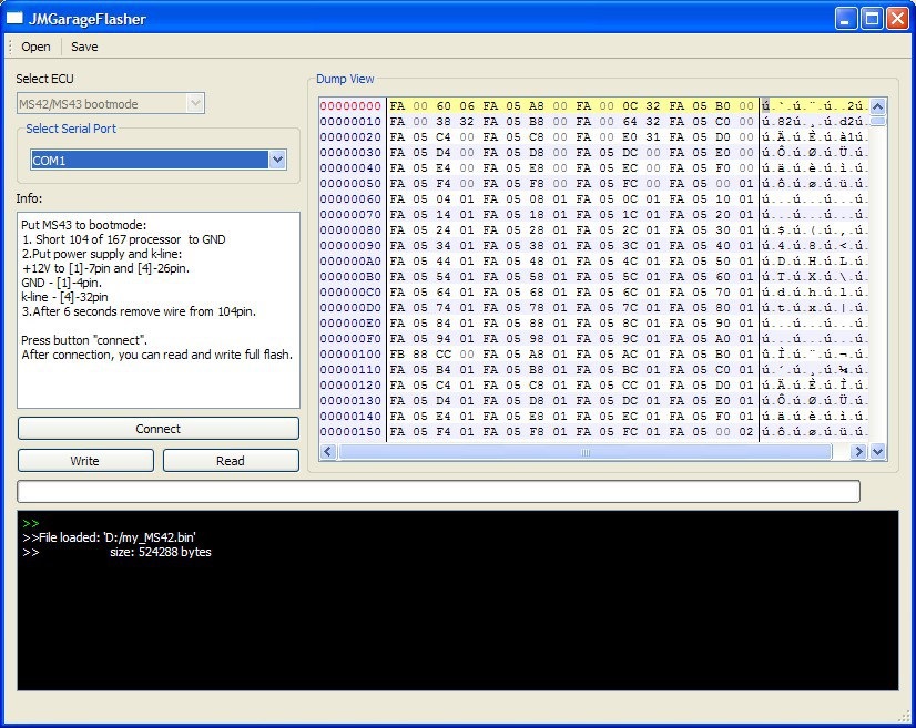
- JMGarageFlasher (boot mode) + k-line adapter. Read and write all flash memory. The program is completely free. Download can be here (18.1 MB).
JMGarageFlasher is a small free utility written using the QT library. The utility allows to read all flash memory AM29F400BB of the Siemens MS42 / MS43 control units in the boot loader mode. Works via k-line adapter. (At the moment the version is still raw, and has bugs, but work is underway and soon there will be a stable version)
After the control unit is entered into bootloader mode, it is necessary to press the "connect" button. "Connecting" with the block, the program allows you to perform a read and write operation by clicking on the "read" and "write" buttons respectively.
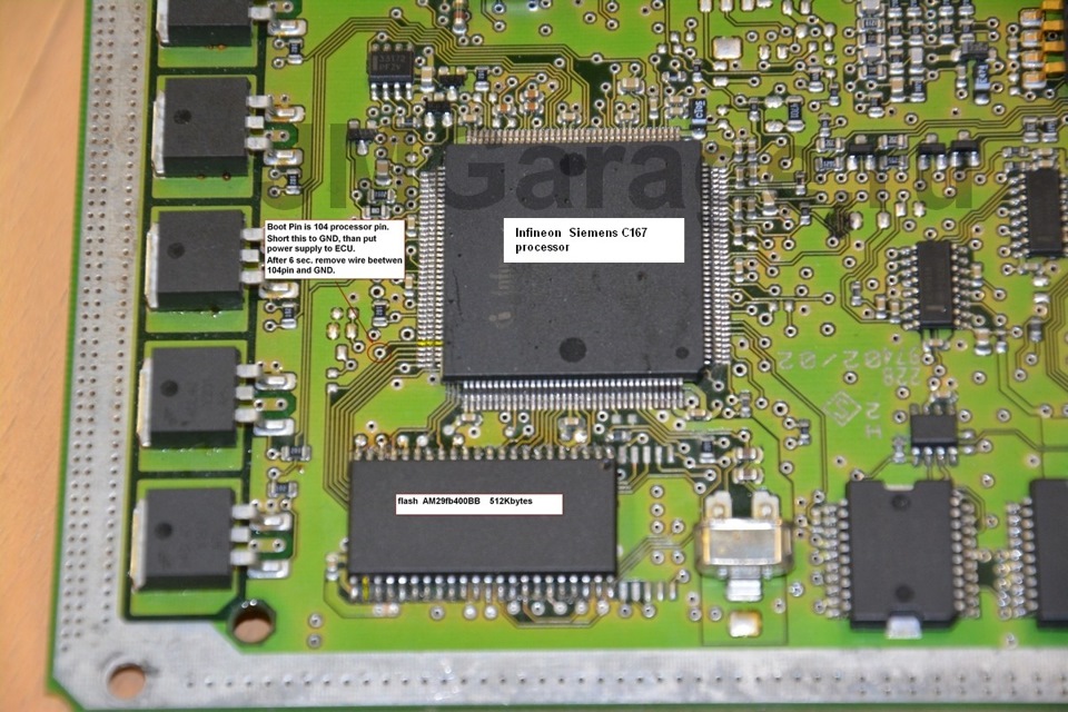
The entire firmware of the MS43 control unit is located in the external flash memory of AMD29F400BB, located on the board next to the C167 processor. The flash size is 512KB.
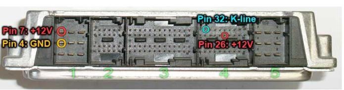
In the case of working with the unit on the table , it is necessary to supply power to the computer connector and the k-line.
1-4 — computer weight (any of the contacts can be used)
1-7- "+ 12V"
4-32 — K-Line
4-26- "+ 12B" ignition
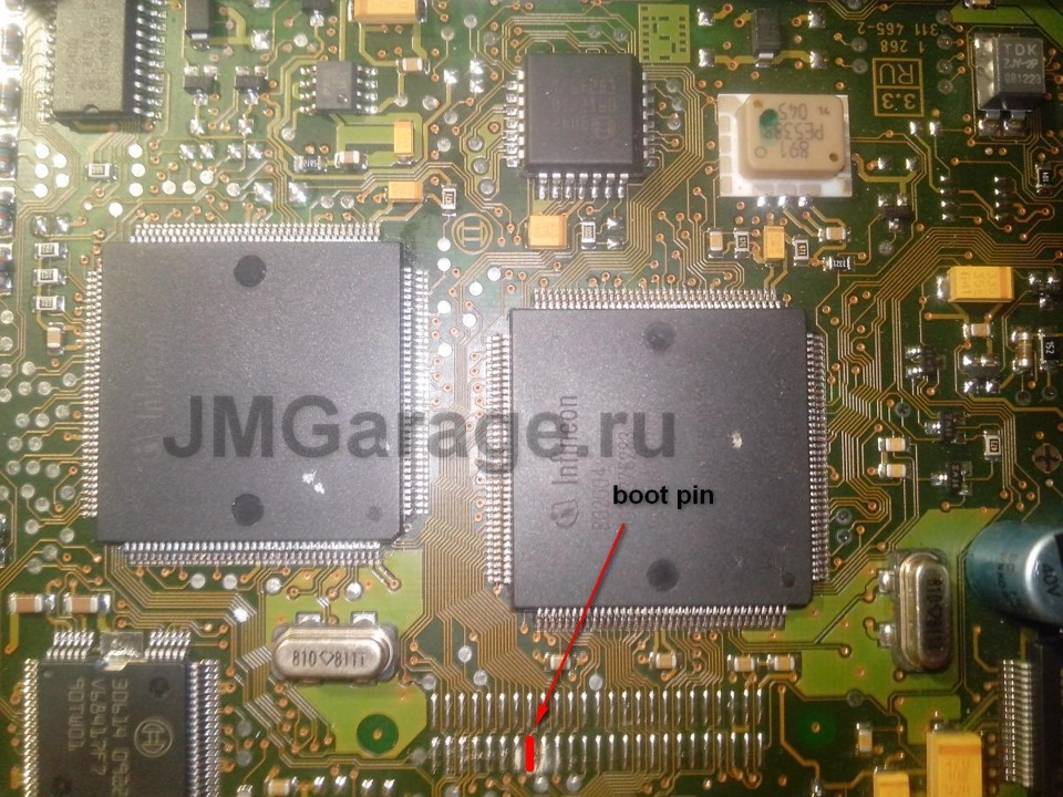
To enter the processor in the boot mode , 104 output of the C167 processor must be interconnected. It also outputs 27 feet of the flash memory AM29F400BB to the ground via a resistor of the order of 10KΩ before the supply voltage is applied to the computer. See photo above.
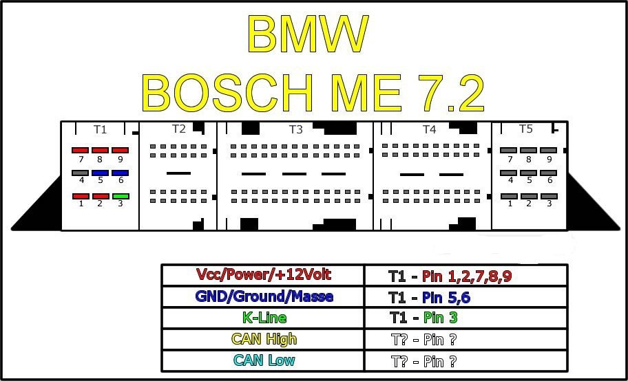
For BOSCH ME 7.2 bootmode programming :
Let's consider basic maps and firmware parameters , necessary for detuning the non-standard (modified) motor M52TU and M54.
All firmware parameters are divided into 4 main categories:
1) General information
2) Fuel / mixture
3) Ignition
4) Timings / Vanos
You can edit the firmware by WinOls and TunerPro .
All examples in the record are made in the editor WinOls . This editor you can download here (free hacked version, with Russifier). TunerPro free version you can download here (2.74 MB).
General Settings
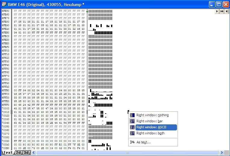
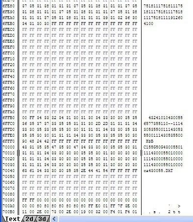
The calibration data of MS43 firmware starts at address 0x70000.
The software version is at the beginning of the calibrations and is repeated 3 times. By default, in the WinOls editor, the values at the desired address are illustrated in the form of bars. In order to see the digital values of the software version, you must switch to ASCII mode by right-clicking in the dump field and selecting "ASCII".
software version in firmware MS43
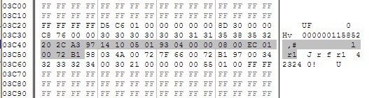
VIN is encrypted, but it can be found by starting bytes — "20 2C A3". VIN takes 19 bytes, starting with "20". The number itself is 18 bytes, the 19th checksum.
ISN is located in the address range 0x3ED0 and occupies 6 bytes. ISN is easy to find by preceding "FF FF" bytes and separate significant 6 bytes of the ISN itself (see image).
To bring the computer to the factory (initial) state, in the ISN area, write "FF FF FF FF FF FF". The "clean" ISN area allows you to link any MS43 / MS42 to any working EWS using INPA. During the synchronization operation in INPA, the computer will copy the ISN data from EWS to its firmware and synchronize in the normal mode. This method is good in the absence of EWS programming tools, but it is required to synchronize the immobilizer from another machine.
Fuel / Mixture
Siemens MS42 / MS43 have an extensive set of fuel injection settings. Such a variety and flexibility allows you to calibrate the unit for almost any task.
Basic constants:
C_TI_MIN_IV is the minimum injection time in milliseconds. The controller never opens the nozzle for less than a predetermined time. As a rule, it is equal to 0.352 msec.
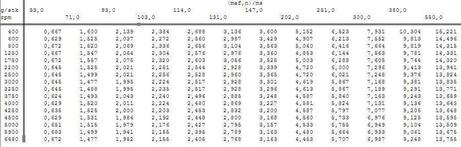
IP_TIB (12 × 16) — basic injection in msec. In fact, the static nozzles.
Axis 1 — revolutions
Axis 2 — air flow rate (gr / sec)
The table for the BMW 2.2 engine is as follows:
If you want to adjust the mixture, then start with this card. From this value, all calculations based on the injection time in the normal operation mode are repelled, when the air flow sensor is good. In the event of a fault in the DMRV, the computer receives the airflow value from the map IP_MAF_1_DIAG.
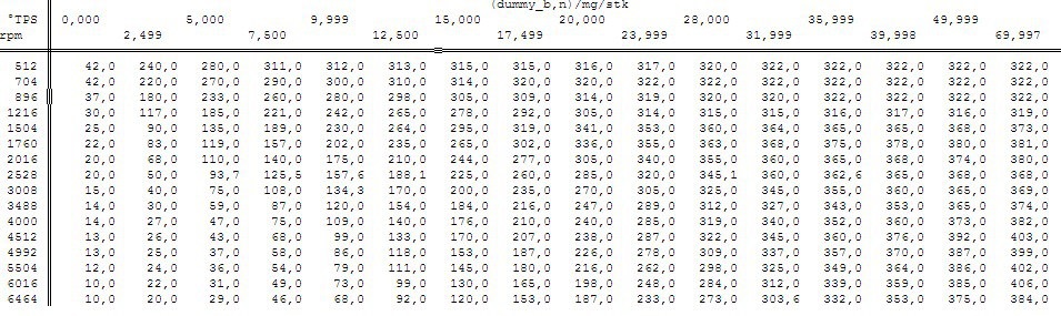
IP_MAF_1_DIAG (16 × 16) . Forecast (reception) of the air flow by the position of the throttle.
The map works if there are problems with the DMR.
Axis 1 — revolutions
Axis 2 — tps, throttle position
This is the so-called alpha / n card. Many tuners use it when installing multidrop intake and, accordingly, removing the DMRV from the system. With this approach, the load on the motor (air flow) is calculated very inaccurately and as a consequence, the output fuel-air mixture and ignition leave much to be desired.
IP_TI_ADD_DLY (1 × 8) injector dynamics.
The map displays the opening time of the injector depending on the voltage on the battery. For a qualitative adjustment, the map must be edited when installing injectors other than the factory ones or changing the pressure in the fuel rail.
The pressure is higher — the opening time of the injector is longer.
The voltage in the network is higher — lower the opening time of the injector.
![]() " />
" />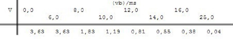
Dynamics of injectors
Ignition
Partial and full loads
IGAB_IVVT is the ignition angle at partial and full loads with vanos running. This is the calculated value (variable), which is used for further calculations of the target PEL ( IGA — the same ignition timing).
Calculation formula:
IGAB_IVVT = (IP_IGA_TCO_1_PL_IVVT__N__MAF — IP_IGA_TCO_2_PL_IVVT__N__MAF) * IP_FAC_PL_IVVT__TCO__TCO_ST + IP_IGA_TCO_2_PL_IVVT__N__MAF
IP_IGA_TCO_1_PL_IVVT__N__MAF — UOZ map with cold motor (TCO1)
IP_IGA_TCO_2_PL_IVVT__N__MAF — UOZ map with hot engine (TCO2)
In version a2l for 430056 there are 2 maps with RON_91 and RON_98. Those. there are versions of MS43 where repel from RON_91 and RON_98. Depending on the adaptations for detonation, the block switches (with the engine warmed up) to the 91st or 98th map.
IP_FAC_PL_IVVT__TCO__TCO_ST — the factor (weight) of the difference between these two cards (for TCO1 and TCO2).
When calculating the target IGA , it is necessary to take into account: the temperature correction IP_IGA_MAF_N__N__MAF * IP_FAC_TIA_TCO__TCO__TIA and the transition angle of ignition ID_IGA_TRA_KNK_N_MAF * ID_FAC_IGA_TRA_TIA
Those. the total IGA is obtained by the formula:
IGA = IGAB_IVVT + (IP_IGA_MAF_N__N__MAF IP_FAC_TIA_TCO__TCO__TIA) + (ID_IGA_TRA_KNK_N_MAF ID_FAC_IGA_TRA_TIA)
When tuning it is worth turning maps IP_IGA_RON_91_PL_IVVT__N__MAF and IP_IGA_RON_98_PL_IVVT__N__MAF for the warmed-up engine and the 91st, 98th octane, respectively.
Start
IP_IGA_ST__N is the UDP map at the start,
IP_IGA_TCO_ST__TCO — correction of the POC at the start
IGA (at the start) = IP_IGA_ST__N + IP_IGA_TCO_ST__TCO
Frequent throttle change
IP_IGA_PU__N__TCO — PTS when moving the throttle, the so-called tralling trottle.
Idling
Basic PTS at XX with working VANOS:
is calculated on the basis of 2 maps IP_IGA_TCO_1_IS_IVVT__N__MAF and IP_IGA_TCO_2_IS_IVVT__N__MAF for the cold (TCO1) and warmed (TCO2) motors respectively and according to the factor from the map IP_FAC_IS_IVVT__TCO__TCO_ST .
In the event of a VANOS failure, the unit moves the shafts to the extreme positions, sets an error and the UOZ at XX is calculated on the IP_IGAB_IS__N__MAF map.
_iga_optm_ — maps, calculating the optimal POC when running the anti-slip system, transient modes when switching gears and the like in which you want to extinguish the moment by decreasing the UOZ. Those. the system calculates the optimal moment for the anti-bug (for example) and on the basis of this optimal moment chooses the maximum possible UOZ — iga_optm. When tuning these parameters it is better not to touch.
Source: jmgarage
Zoom
Dynamics with the soul (BMW)
To be continued, for the time being we will learn these lessons, in the future we will try to delve into concepts and definitions in order to dot the "I".
Thank you all for attention! See you soon! Happy Easter holiday.